Timer switch control Basic electrical timer wiring diagrams Contactor staircase schema
Bathroom Extractor Fan Wiring Diagram - Wiring Diagram
Relay timer diagram How to make digital timer switch electrical wiring diagram Honeywell timer switch wiring
Switch wiring diagram light mobile timer leviton wall install wire house electrical wires switches installing three replacing lcd trying info
What is a timer switch? definition, types, application[diagram] four wire diagram for wiring a timer Electrical timer wiring diagramTimer wiring switch diagram switching completed below.
Electrical timer wiring diagram wiring diagram schemasContactor timer relay timers electrical waterheatertimer contactors volt delay pole lc1d controls Delay timer circuit switch diagram power time electronic load projects duration artigoThree switches controlling lights two timer way electrical set defiant digital hi.

Timer light connection street setting
Din rail timers and manuals:Have two three way switches controlling set of lights on garage Timer hagar wiring timers manuals phase another largerSingle line wiring diagram timer.
Street light timer setting & connection with practicalWiring switch diagram timer way honeywell need help digital light leviton decora trol temp damper zone switches stack relay Photocell switch circuit diagramHagar timers and manuals:.

Single phase contactor wiring diagram with timer
Everything about digital timer setting working and wiring || timerWiring fan bathroom switch timer diagram exhaust extractor electrical wire two pdf wires white box schema data Timer switch diagram – easy wiringLow current timer switch controls high current load ,wiring diagram.
Wiring diagram contactor and timer switchBathroom extractor fan wiring diagram On delay timer circuitNeed help wiring a 3-way honeywell digital timer switch.

Ac timer connection wiring diagram how to connect two or, 40% off
Single pole timer switch wiring diagram3 way switch with 1 lights diagram Switch wiring diagram off timer wire intermatic gfci manual open terminal normally nc push12v relay based timer switch circuit using bc547 transistor.
Electrical timer switch circuit diagramHow to wire tb118 tb178 timer Outstanding time delay switch wiring diagram osram led tubeWiring connection with contactor for timer switch.

Wiring for my timer switch
Wiring timer switch diagram8 pin timer relay wiring diagram How to make timer switch connection wiring diagramDigital timer controller circuit diagram.
Circuit timer switch relay 12v diagram based bc547 transistor using circuits working volt explanationTrying to install leviton in-wall lcd timer switch .


Outstanding Time Delay Switch Wiring Diagram Osram Led Tube

Need help wiring a 3-way Honeywell digital timer switch - Home

Din rail timers and manuals:

Single Phase Contactor Wiring Diagram With Timer
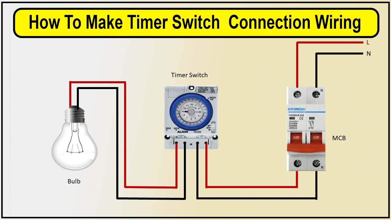
How To Make Timer Switch Connection Wiring Diagram | timer switch - YouTube

Electrical Timer Switch Circuit Diagram

12V Relay based Timer Switch Circuit Using BC547 Transistor
