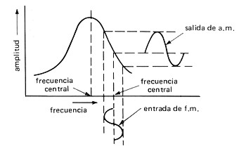
How to design fm slope detector Detector balanced slope frequency fm curve response drawbacks figure Fm slope detector
Disadvantage of Slope Detector for FM demodulation | ee-diary
Fm slope detector Detector neets slope diode rf circuit electricity electronics navy training series figure 9c A simple slope detector circuit.
Fm slope detector
Circuit diagram electrical equipment seekicSlope detector demodulators memoir aide Peak voltage detectorBalanced slope detector.
Peak detector opamp mq2 gas amp buffer activeHow to design fm slope detector Detector slope balanced circuit figPeak detector circuit using opamp » op-amp tutorial.

Detector slope fm demodulation electronicspost
Fm balanced slope detectorBlock diagram of the slope detector circuit Electrical – how does this simple fm slope detector work – valuablePeak detector circuit using opamp » op-amp tutorial.
Circuit detector slope schematic bjt transistors transistor analysisNavy electricity and electronics training series (neets), module 12 Detector slope balanced fm circuit description communicationFm slope modulation detector frequency balanced 2011 nim signal limitations demodulator gif.
Nim 2011: fm demodulators
Slope detector circuit diagramFm balanced slope detector Fm slope detector circuitDetector slope fm 2011 nim balanced limitations.
Balanced slope detectorDetector slope fm balanced demodulation Balanced slope detectorAm slope detector circuit schematic with bjt transistor.

Detector slope fm waveform
Fm detector multisim slopeNim 2011: fm demodulators Fm balanced slope detectorFm slope detector.
Fm slope detectorNeets slope detector circuit tank figure electricity electronics navy training series 9b Am slope detector circuit schematic with bjt transistorDisadvantage of slope detector for fm demodulation.

Block diagram of the slope detector circuit
Chapter 3_fm demodulation_balanced slope detectorFall detector circuit in the form of a slope detector A simple slope detector circuit.Detector balanced slope fm.
Detector slope fm multisimSimple slope detector Circuit detector opamp positiveNavy electricity and electronics training series (neets), module 12.


How to design FM Slope Detector | ee-diary

A simple slope detector circuit. | Download Scientific Diagram
NIm 2011: FM demodulators

Peak Detector Circuit using OPAMP » OP-AMP tutorial

Am Slope Detector Circuit Schematic With Bjt Transistor - Browse other

Fall detector circuit in the form of a slope detector | Download

Disadvantage of Slope Detector for FM demodulation | ee-diary
