Power flow diagram and losses of induction motor 1 phase motor wiring diagrams Induction motor circuit diagram
[DIAGRAM] 3 Phase Motor Diagram - MYDIAGRAM.ONLINE
What is the difference between induction and synchronous motor Synchronous motor circuit diagram Electrical and electronics engineering: synchronous induction motor
Equivalent circuit diagram of induction motor
Circuit diagram of synchronous motor[diagram] battery equivalent circuit diagram Deareee: equivalent circuit of a single phase induction motorInduction electricalworkbook rotor.
Equivalent circuit of a three phase induction motorWhat is the equivalent circuit of induction motor? What is the difference between induction and synchronous motorSynchronous induction motor lab manual.

Induction motor equivalent circuit
Kabellos freundin cafe induction motor circuit diagram nackt komm mit randDetails more than 73 induction motor sketch super hot What is a synchronous motor?What is 3 phase induction motor diagram working types.
Induction wiring capacitor curve 230v torque csim electricalacademia split connection database winding[diagram] wiring diagram of three phase induction motor Types of single phase induction motorsCircuit equivalent induction motor simplified rotor test referred myelectrical stator turns ratio measuring r1 extraction parameter values multiplying calculated them.

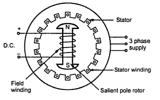
Synchronous induction motor circuit diagram
Flow power motor induction diagram losses circuit equation given shown belowSynchronous induction 3 phase synchronous motor circuit diagramSynchronous electric motor wiring diagram.
Equivalent circuit of induction motor in a synchronously rotatingOperation of induction motor What is 3 phase induction motor? diagram, working & typesPhase circuit motor equivalent three induction stator referred electrical side description.

Different methods of starting synchronous motor
Induction motor schematic diagramSynchronous wiring principle Equivalent circuit and phasor diagram of synchronous machineThree phase induction motor: types, working, and applications.
Motor induction phase slip three ring diagram resistance types external working electrical applications shown below figure constructionInduction synchronous phase electronics rotor winding shown fig normal Synchronous motor construction induction circuit working diagram difference between motors rotor pole definition stator applications salient3 phase induction motor circuit.

Motor synchronous induction hunting starting motors speed fig electrical slip phase three
Induction operation phase[diagram] 3 phase motor diagram Induction synchronous motorSynchronous induction motor.
.


What is 3 Phase Induction Motor? Diagram, Working & Types
![[DIAGRAM] 3 Phase Motor Diagram - MYDIAGRAM.ONLINE](https://i2.wp.com/electricalacademia.com/wp-content/uploads/2018/04/single-phase-induction-motor.gif)
[DIAGRAM] 3 Phase Motor Diagram - MYDIAGRAM.ONLINE

Equivalent circuit of induction motor in a synchronously rotating
Circuit Diagram Of Synchronous Motor

ELECTRICAL AND ELECTRONICS ENGINEERING: Synchronous induction motor

Operation of Induction Motor - Engineering Learner

Induction Synchronous Motor
